![]()
A report of the State of California, California Coastal Commission to the National Oceanic and Atmospheric Administration pursuant to NOAA Award No. NA90AA-D-CZ492.
This document was prepared by the staff of the California Coastal Commission to discuss techniques which may eliminate or reduce the adverse effects of grading along the California coast. This report has not been approved by the Commission.
Grading is the alteration of natural landforms through removal and/or addition of soil undertaken to make a site safe or suitable for construction or development. Unfortunately, grading often results in negative alteration of the environment. Visual degradation caused by grading is often dramatic in mountainous areas and along coastal bluffs where flat areas have been created by grading. Grading may also disturb the natural habitats of plants and animals in areas on or near a project where grading occurs. The large areas of exposed earth at sites where grading has occurred can lead to increased erosion and siltation, as well as shifts in depositional areas. Changes in sedimentation rates and patterns can result in contamination of surface and groundwater systems, which in turn may result in lower quality of public drinking water as well as pose a threat to the stability of an environmentally sensitive habitat.
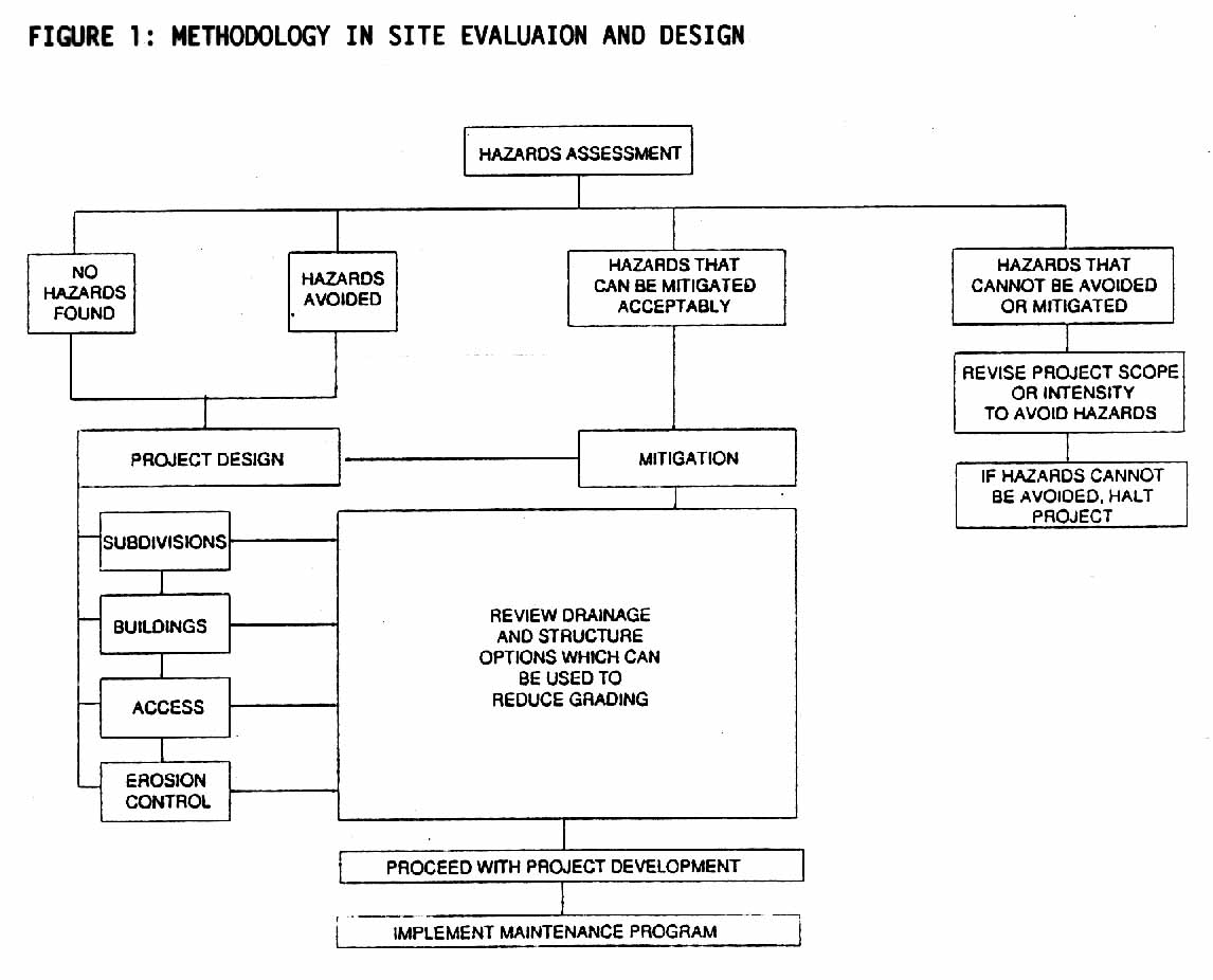
Although some grading is required for most construction projects, the California Coastal Commission is concerned about unnecessary or excessive grading and its effects on the coastal environment. Various designs and construction techniques exist to lessen the extent and effects of grading. Figure 1 illustrates the key steps in project planning and development where grading can be reduced.
Even with carefully planned development, most sites will require some grading. Engineered structures used often in conjunction with drainage controls may be used to stabilize slopes and allow construction with minimal grading. The method of stabilization is chosen based upon evaluation of the type of hazard involved, magnitude of the problem, potential triggering mechanisms, threat to life and cost.
The primary focus of this paper is on the various engineering techniques to stabilize a site with minimal landform alteration. This discussion is not intended to replace professional site inspections or designs by engineering geologists and civil engineers. The techniques discussed here should be considered only after all planning and design options have been exhausted.
It also must be recognized the some hazards cannot be mitigated sufficiently to make a site safe for development because the environmental or engineering costs of the mitigation are too high, or, in some cases, because no solution currently exists. Furthermore, not every site can support the same scale and intensity of development, so even if a site is developable, it might not be suitable for a specific project. The issues of land use and site planning will not be discussed in this paper; however, these issues have a very direct and obvious impact on grading and the level of landform alteration required for project development.
In many areas along the California coast, safe and environmentally acceptable projects can be designed because the sites have little topographic relief, have easy access and have no identified geologic hazards. However, many locations have one or more development constraints and even with the most innovative site designs, some slope modifications will often be required and engineered structures may be needed to make a site suitable for development. There are many engineering techniques to solve stability problems, all of which require varying degrees of natural terrain alteration.
The method of stabilization is chosen based upon evaluation of the type of hazard involved, magnitude of the problem, potential triggering mechanisms, threat to life and property, and cost. Effective stabilization methods should only be determined after an evaluation of geologic and hydrologic conditions is completed by a certified engineering geologist and a registered professional engineer.
Common methods of stabilization that often involve extensive grading are slope alteration and complete removal of a hazard. Slope alteration as a method of stabilization commonly involves variations of the cut and fill technique. The stability of a slope is increased by reducing the driving forces (unloading or removing the top of the slope) and/or increasing resistant forces (placement of fill at the toe of the slope) along potential failure surfaces.
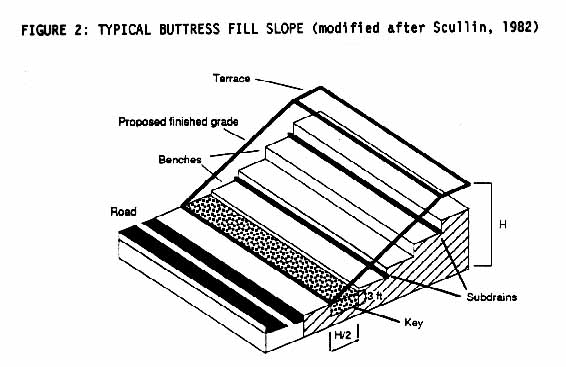
The most common technique used to stabilize slopes is a buttress fill (Figure 2). Buttress fills are used to stabilize poorly consolidated or incompetent bedrock, and have been used frequently for the relatively weak sedimentary formations in southern California. A typical compacted fill buttress is constructed by removing the outer face of a cut slope and replacing it with engineered, compacted fill. The buttress fill mass is designed specifically to retain the slope behind it, usually with a factor of safety of at least 1.5 (where a factor of safety less than 1.0 is considered grossly unstable). Such a buttress is "keyed" into competent underlying materials to provide adequate support. Key widths along the toe of slope typically range between 15 and 200 feet. Buttress fill slopes are generally constructed with a finished grade of 2:1 (horizontal to vertical); however, steeper gradients are sometimes acceptable if sufficient shear strength of the resultant fill slope is attained (Frankian, 1983).
"Stabilization fills" are similar to buttress fills, except the fill mass is not designed to support surfaces of weakness or deep seated landslides. Rather, the fill is constructed along a slope face to mitigate surficial slope failures, such as ravelling, erosion and rockfalls. The base width of stabilization fills is commonly half the height of the slope.
Buttress fills involve large amounts of grading and disturb large areas during construction. Earth removal and, the sharp, unnatural lines of a finished buttress slope are apparent when compared to the irregular contours of more natural landforms. Contour grading can be used to reduce the visual impacts of the graded areas by designing the finished slope face to more closely conform to natural contours. Contour grading does not reduce the quantity of grading, but can create rounded or undulating landforms designed to resemble the unaltered slopes on and adjacent to the construction site.
The Department of Planning for the City of Los Angeles has prepared planning guidelines for contour or landform grading, which were adopted by the City Council (City of Los Angeles, 1983). These guidelines are also used in some neighboring communities and in portions of Los Angeles County.
Aside from aesthetic impacts, earth exposed during the construction of a buttress can cause accelerated erosion and siltation when drainage and soil retention methods are not utilized during grading. Sheetwash and gullying remove soil from exposed slopes as drainage patterns develop within the slope and along low-lying areas at the base of the slopes, resulting in extensive siltation at adjacent locations. However, utilization of proper erosion control methods (e.g. sandbags, hydroseeding, geofabric barriers) during grading will reduce erosion and siltation.
One of the initial stages in stabilizing a slope is to establish control of surface and groundwater systems (Gedney and Weber, 1978). Water control is generally maintained through installation of surface and subsurface drainage devices within and adjacent to potentially unstable slopes. Surface and subsurface drainage design must include consideration of the effects of surface runoff and groundwater migration on the stability and water quality of adjacent sites (Powers, 1991; Gedney and Weber, 1978). In landslide areas drainage design is especially important because an influx of water from irrigation, disposal of sewage effluent or leaks from water storage devices can raise groundwater levels, increase pore-water pressure, and load slopes, thus causing an increase in failure potential (Broms and Wong, 1991). Control of surface and groundwater flow is also important in minimizing erosion and siltation both on and off site. A properly designed drainage system should increase slope stability and decrease erosion and siltation.
Drainage control is particularly important in bluff top stabilization along the coast. Bluff top stabilization is often best attained by designing final site contours that direct surface water away from the bluff to storm drains (Kuhn, 1984). Designing a surface contour that directs water away from the bluff results in reduced infiltration and groundwater recharge in areas adjacent to the bluff, thus reducing the risk of bluff failure.
Runoff and infiltration of water along a slope or over a bluff face can often be reduced by planting vegetation on top of the slope or bluff, as certain types of vegetation anchor soils, which in turn reduces erosion. A vegetative cover that does not require irrigation must be chosen because the infiltration of the water from irrigation can result in increased failure potential. However, vegetation is ineffective in stabilizing slopes where movement has already begun, so in many situations, vegetation cannot be used as the sole stabilization method.
Surface Drainage Systems
Surface drains and/or landscape design are used to direct water away from the head and toe of cut slopes and potential landslides, and to reduce infiltration and erosion in and along a potentially unstable mass. Surface drains are instrumental in controlling erosion of slopes and in drainage control adjacent to fill slopes.
The most common surface drainage devices used in prevention of slope erosion and failure are terrace drains. Terrace drains are commonly 3 to 5 feet wide, 18 inch deep, V-shaped structures that are paved with 3 inches of reinforced concrete or gunite. A problem with terrace drains is that often they are left exposed, which degrades the aesthetics of a hillside. This can be minimized by concealing the structures with vegetation. Pipe drains buried at the surface can perform the same function as terrace drains, but are not advised because buried pipes often get plugged and drainage control is hindered. Terrace drains also get clogged by debris and drains are effective only if they are periodically cleaned and maintained.
Surface water control on sites that are already developed may require construction of drains or repaving of areas such as parking lots or accessways to direct water away from slopes or a bluff. However, at many sites, construction or reconstruction of water control devices may not be possible without reducing the stability of the bluff face. In these situations, the only available drainage control may be to contain and redirect runoff over the face through channels or piping that extend to ocean at the toe of the slope. If conduits are used to divert runoff, they must be maintained regularly and replaced immediately should a leak develop.
Subsurface Drainage Systems
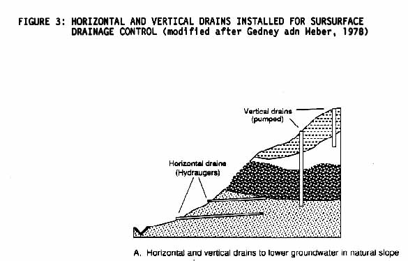
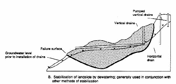
Stability of a slope generally increases with decreased seepage, pore-water pressure, and slope weight, all of which may be achieved with installation of subdrains (Gedney and Weber, 1978). The main functions of subdrains are to remove subsurface water directly from an unstable slope, to redirect adjacent groundwater sources away from the subject property and to reduce hydrostatic pressures beneath and adjacent to engineered structures (Scullin, 1983). Control of subsurface drainage is generally attained by installing a network of horizontal and/or vertical subdrains which channel and remove groundwater from potentially unstable slopes (Figure 3). Many slopes cannot be effectively dewatered and therefore, this technique cannot be applied everywhere.
An important consideration in design of all drainage systems is short and long term maintenance. Over time drainage systems can clog; pipes can corrode or rupture, and other problems can arise which would prevent the system from functioning properly. Such problems can counter or diminish the beneficial effects of the drainage system, possibly leading to slope damage or failure, structural damage or the need for extensive remedial grading.
Rarely is drainage the only control device utilized in stabilizing a large slope (Barrett, 1980; Broms and Wong, 1991). The described drainage systems are generally installed along with other mitigation devices to increase slope stability. The methods outlined in this section require various amounts of grading, however, the included techniques generally result in less landform alteration than does cut and fill. The differences in grading and degree of landform alteration are generally reflected in the installation method and the size of a particular engineered mitigation device. This section includes descriptions of the effective applications, limitations, installation, and maintenance of various engineering devices.
Ground Inclusions
A ground inclusion is a metal bar that is driven or drilled into competent bedrock (rock which is not highly fractured or broken up) to a provide stable foundation for structures such as retaining walls and piles, or to hold together highly fractured or jointed rock. Ground inclusions can be used at times as alternatives to the foundation piles which are typically used to support structures within mountainous or steep areas. The size and thickness of a retention system can also be diminished by using a system stabilized with inclusions (Juran and Elias, 1991). Elimination of deep foundations and a reduction in required size of a support structure make the use of inclusions an important method in reducing grading and minimizing visual impacts of a project.
Three common types of ground inclusions are ground anchors, soil nails and rock bolts. Permanent ground anchors are tendons which are placed in competent rock or soil to control displacements and provide vertical and lateral support for engineered structures and natural slopes (Juran and Elias, 1991). Anchors are frequently used in waterfront structures and to tie-back retaining walls to prevent failures due to rotational loading or failures due to buoyant forces of water.
Soil nailing is a soil reinforcement technique that places closely spaced metal bars or rods into soil to increase the strength of the soil mass (Broms and Wong, 1991) (Figure 4). Soil nails are either installed in drilled bore holes and secured with grout, or they are driven into the ground. The soil nails are generally attached to concrete facing located at the surface of the structure. The function of the facing is to prevent erosion of the surface material surrounding the soil nails, rather than provide structural support (Broms, 1991). This facing can be constructed to mimic the look of the surrounding landform and provide spaces for vegetation; however, the facing will not be the same as the existing top soil.
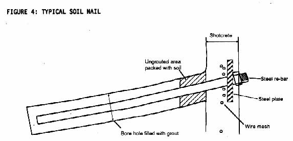
Soil nailing is a method that can be used to control shallow landslides. In these situations, movement is controlled by inserting 15 to 30 mm bars in drilled holes, generally spaced 2 meters apart, which are then filled with grout. The bars must extend beyond the failure zone into stable rock, and are typically between 3 and 10 meters in length (Broms and Wong, 1991).
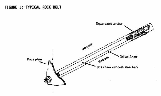
Rock bolting is a method of securing or strengthening closely jointed or highly fissured rocks in cut slopes by inserting and firmly anchoring a steel bar in predrilled holes that range in length from less than one meter to about 12 meters (Bates and Jackson, 1987) (Figure 5). Rock bolts generally have heads that expand following installation and are classified according to their method of anchorage: expansion, wedge, grouted and explosive (Bates and Jackson, 1987). Like soil nails, these bolts generally are attached to some type of facing.
Limitations and considerations for the use of ground inclusions are usually in the area of long term stability. Metal inclusions are generally protected from corrosion by a sealant or grout; however, in environments where there is frequent interaction with groundwater, breakdown of inclusions is accelerated. Also, the effects of creep on the structural integrity of a wall or other anchored systems must be considered in the design of a structure (Juran and Elias, 1991). There are specific soil liquidity and plasticity limits that are not suitable for the use of anchors (Cheney, 1988). Construction above the anchors may be limited, and excavation would undermine the stability of any anchors present (Cheney, 1988).
Piles
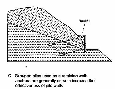
Piles are long, relatively slender columns positioned vertically in the ground or at an angle (battered) used to transfer load to a more stable substratum.(Figure 6). Piles are often used to support or stabilize structures built in geologically unstable areas. The effectiveness of piles is increased dramatically when they are incorporated into an anchored stabilization system. In addition, piles are used to minimize the effects of scour and undercutting along the foundations of waterfront structures.
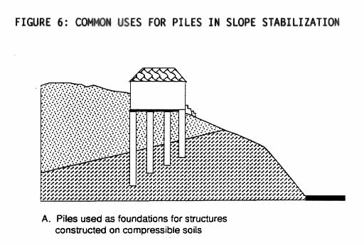
Piles are either driven into the ground or they are are placed in drilled holes. Piles placed in drilled holes directly support the weight of a structure. Driven piles are installed in soft or loosely consolidated material and often do not directly absorb the load of a structure. Rather, the bearing capacity and stability of the soil increase as the soil surrounding the piles densifies due to a decrease in void ratio equivalent to the volume of soil displaced by a driven pile (Spangler and Handy, 1982). Piles can only be driven in carefully studied locations because slope failure can be induced by the vibrations caused by pile driving. Installation of bored piles generally does not alter the stability of the in situ rock or soil (D'Appolonia and others, 1975).
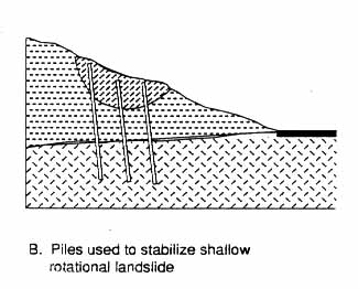
One major benefit to the use of piles is that, unless they are used as a retaining wall or to support a structure on a steep slope, they will not be visible after installation. When they are used for subsurface stability, they will not cause massive landform alteration or long-term surface disturbance. When piles are used to stabilize landslides, they are only effective if they extend to depths below potential failure planes and if the piles have sufficient strength to support the full load of the slide mass. If the failure plane and slide mass cannot be defined with any certainty, it may be difficult to design an effective pile stabilization system. For small, well-defined slides, piles can be very useful and effective.
Retaining Walls
Retaining walls are engineered structures constructed to resist lateral forces imposed by soil movement and water pressure (Dismuke and Cornfield, 1991). Although grading is necessary for construction of all retaining walls, the excavation takes place predominantly along the toe of a slope, with the upper slopes requiring little, if any alteration. Since cutting the toe of a slope can destabilize the slide, the construction of retaining walls at the toe of a slide should be undertaken only after it has been determined that the slide can remain stable during construction. Retaining walls are commonly used in combination with fill slopes to reduce the extent of a slope to allow a road to be widened and to create additional space around buildings. Retaining walls are also used as protection against the erosive forces of water and as a method of slope stabilization along highways, railroads, and construction sites (Dismuke and Cornfield, 1991). Retaining walls are also used along the coast for protection against wave damage and bluff failure. Both vertical walls and revetments can be used for protection, and the design for each must consider beach scour, storm wave height, wave run-up, tide level and future sea level conditions, as well as the geologic properties of the bluff face.
Retaining walls can be separated into categories based upon the force parameters acting on the structure to provide stability. The three types of retaining walls are anchored, gravity, and cantilever. All three can be used as coastal structures and for slope stabilization.
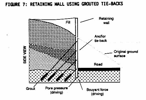
An anchored wall gains stability through use of tie-back systems attached to its face that oppose the tendency for sliding within an unstable slope. Additional stability can be attained when anchored walls are installed on an angle, which compresses the soil and increases stress along the failure plane (Morgenstern and Sangrey, 1982).
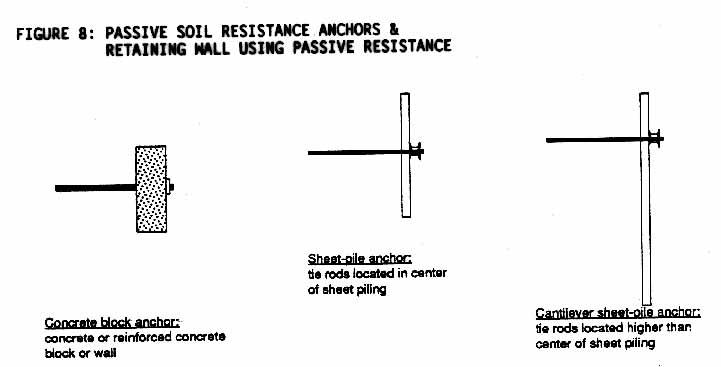
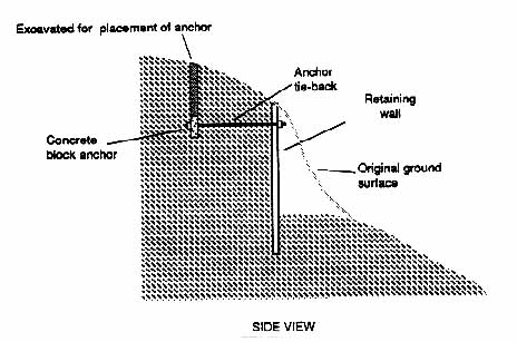
Anchors used in restrained structures are placed upslope from the wall and are connected to the wall by a steel tension bar or cable (Morgenstern, 1982). Inclusions are commonly used to stabilize retaining structures (Figure 7) as are passive soil anchors such as cement blocks or sheet piles tied to the retaining structure (Figure 8). Anchored walls are an effective method of stabilization only if the anchors are installed beyond the unstable portion of a slope in stable material and if the tendon is protected from corrosion.
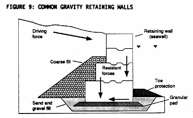
Walls that are not tied to a competent unit but obtain their stability through the weight of the structure are referred to as gravity structures (Figure 9). Gravity structures are generally less that 10 meters in height and only used to stabilize very small landslides or slumps. Typical gravity walls are crib or gabion structures. (Crib walls are vertical or near-vertical walls constructed out of pre-formed, interlocking beams and backfill material; gabion walls are constructed out of interconnected wire mesh boxes.) The wall elements may be tied into the slope to prevent movement, however, most of the stability for the wall comes from the the weight of the structure. Gravity walls are rarely used to stabilize large slides because the required depth of excavation makes the solution too expensive. In addition, deep excavations for construction of a retaining wall may add to increased instability of a slope during construction (Morgenstern and Sangrey, 1982).
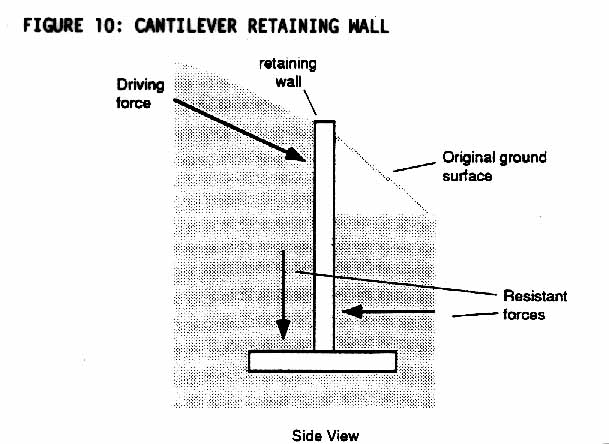
A cantilever wall penetrates to a depth beyond the failure surface (Figure 10). Cantilever structures are different from gravity and anchored structures in that they derive their stability from the depth of penetration and the stiffness of the structure. Support and stability is maintained by the soil in which the wall is placed. Cantilever walls are not a common method of stabilization because deep excavations often are required and the structures are generally not effective at heights in excess of 5 meters. Both factors limit the use of cantilever walls to mitigation of only the smallest hazards. As a result, cantilever walls are used most often in temporary rather than permanent structures. Cantilever walls are often constructed of sheet pile or bored pile walls, similar to anchored walls, but without anchors.
Soil stabilization and soil improvement include methods that increase the load carrying capacity and resistance of soils by physical or chemical alteration of the soil (Winterkorn and Pamukcu, 1991). Soil properties such as strength, stiffness, compressibility, and the effects of water often change when soil improvement techniques are utilized (Winterkorn and Pamukcu, 1991). Such soil improving and stabilizing techniques include, among others, reinforced earth, geosynthetics, grouting and chemical treatment.
Reinforced Earth
Reinforced earth is a construction system made of a frictional backfill material reinforced with flexible strips and covered with facing elements (Figure 11). A reinforced earth system is generally constructed by layering soil with either metal strips or geosynthetic materials which are brought into tension and resist horizontal deflection. For retaining walls, ends of the strips are bolted to horizontal wall elements during assembly and filling. The method differs from tiebacks in that anchoring is by friction of backfill soil on the metal strips and there is no post-tensioning.
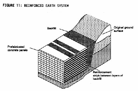
Reinforced earth is used in construction of many different structures, including retaining walls, seawalls, bridge abutments, and occasionally, in slab foundation stabilization on weak soils (Schlosser and Bastick, 1991). Its face can be vertical, as shown in Figure 11, or else sloped or stepped. Reinforced earth has good mechanical flexibility. The use of earth and prefabricated materials makes it a quick and relatively inexpensive stabilization technique. Reinforced earth walls have a particular advantage over concrete and steel structures in that reinforced earth walls can withstand vibrational motion more effectively than rigid retaining structures (Schlosser and Bastick, 1991).
Negative aspects of reinforced earth are that backfilling is required along the entire span of a reinforced earth wall, requiring either grading of the lower hillslope or importation of large volumes of fill material. When used along the coast for shoreline protection, the toe of reinforced earth walls requires protection from wave action. Furthermore, many coastal areas do not have sufficient bluff area to provide the required backfill if such extensive bluff modifications were to be acceptable.
Geosynthetics
Geosynthetics are porous, flexible, man-made fabrics which act to reinforce and increase the stability of structures such as earth fills, and thereby allow steeper cut slopes and less grading in hillside terrain. Geosynthetics of various tensile strengths are used for a variety of stability problems, with a common use being reinforcement of unpaved roads constructed on weak soils. Geosynthetics and a steel or fiberglass reinforced material can be used to increase slope strength, and can also be used to reinforce retaining walls (Yako and Christopher, 1987).
When geosynthetics were first used in construction applications, many of the materials lost their strength when they were exposed to ultraviolet radiation. This problem since has been addressed by the use of newer materials; however there is not enough long-term field information on most of these fabrics to support of refute the laboratory claims. These fabrics can easily be torn by construction equipment and caution must be taken when installing geosynthetics to increase the duration of the fabric's effectiveness. Long term durability is important when geosynthetics are used in slope stability since deteriorated fabrics may cease to function properly, removing extraction and reconstruction of the stabilized slope.
Grouting
Grout is a cement, silicate, or acrylamide based slurry, fluid enough to be poured or injected into soil and thereby fill, seal, or compact the surrounding soil (Scullin, 1983). Grouting is the pressure injection of this slurry through drilled holes into fissured, jointed, permeable rocks and compressible soils to reduce their permeability and increase their strength (Bates and Jackson, 1987). The type and amount of grout that is needed in a stabilization project is generally based upon grain size distribution, density, water content, and chemistry of the soil, as well as desired function of the grout. Grouting is often viewed as a versatile method of ground improvement for application in difficult soil and rock conditions (Winterkorn and Pamukcu, 1991). A common use of grout involves injection of a slurry into incompetent rock to fill void spaces and form a solid stable mass (Winterkorn and Pamukcu, 1991). Stabilization of fractured rock with grout can help to reduce grading in that jointed or fractured rocks can be stabilized through emplacement of grout, foregoing the need to remove the incompetent material.
Another function of grout is to increase the load-bearing capacity of soil by compacting soils, thus providing support for piles and retaining walls, as well as building foundations. Compaction is obtained by placing a dense cement mixture into a compressible soil, which compacts and consolidates the surrounding soil by displacement. Compaction grouting is generally performed after a structure has failed; the injected material then moves to the weakest soil zone causing a pressure displacement of the surrounding soil which then causes upward movement of the overlying structure or soil. Compaction grouting is important in that the in situ soil can be treated and excavation is not required. The success of compaction grouting depends on many factors such as the grouting pattern and grouting pressure. If grout is applied improperly, it can exacerbate the stability problem, so it should be undertaken only under supervision.
Chemical Stabilization
Chemical stabilization is a soil improvement method that increases the load bearing capability by mixing the soil with powders, slurry, or chemicals. Stability is developed in a number of ways; for example, the admixtures can fill soil voids, bond together individual grains, change the permeability of the soil (Gedney and Weber, 1978). The effectiveness and choice of chemical additives are based upon site specific physical and chemical parameters of the natural soil. Lime is perhaps the most common chemical treatment, with cement grout and potassium also being used (Gedney and Weber, 1978). An understanding of the soil chemistry of the site and the precise geometry of the failure surface are the two most important factors in stabilizing a slope utilizing chemical methods.
A potential drawback in using chemical stabilization is that some chemical reactions may reverse, thus limiting the effectiveness of the process as a function of time (Gedney and Weber, 1978). Utilization of a number of the chemical stabilization methods are subject to environmental constraints, as the effects of chemicals on surface and groundwater need to be assessed.
Common to most site stabilization and erosion and siltation controls is that for the systems to remain effective, they must be maintained and possibly even replaced on a regular basis. The long-term effectiveness of a particular engineered structure can be increased dramatically by developing and implementing specific maintenance procedures. During the construction process, operation and maintenance guidelines should be prepared by the project design engineer and engineering geologist which outline specific maintenance needs of all engineered control devices.
Because surface and groundwater changes can have a major effect on slope stability and runoff, one of the most important procedures is to inspect and maintain drainage systems to insure that they continue to function properly. Drainage systems must be effective during the rainy season; therefore, many maintenance plans require that drainage systems be inspected prior to the start of and soon after the end of each rainy season, and that all needed repairs be completed prior to the start of the next rainy season. Some plans require additional inspections following extreme storm events or after a specific amount of rainfall.
CONCLUSION
Various engineering options exist to reduce the amount and extent of grading from that which often occurs with the conventional cut and fill or buttress fill solutions are used. These options include, among others, drainage controls, ground inclusions, piles, retaining walls, reinforced earth, and soil stabilization techniques. These techniques are one part of the larger project planning process. When grading impacts are a significant issue, all planning and design options which avoid the areas that could require extensive grading must be exhausted before these engineering options are considered. Finally, these engineering options should be considered for specific sites only with complete input from a certified engineering geologist and registered civil engineer.
#2239p
REFERENCES CITED
Barrett, R.K., 1980, Use of Horizontal Drains: Case Histories from the Colorado Division of Highways: Papers from the 59th Annual Meeting of the Transportation Research Board, Washington D.C., Transportation Research Board, 21 p.
Bates, R.L., and Jackson, J.A., ed., 1987, Glossary of Geology: American Geological Institute, 788 p.
Broms, B.B., and Wong, K.S., 1991, Landslides in Fang, H., ed., Foundation Engineering Handbook: New York, Van Nostrand Reinhold, p. 410-446.
Cheney, R.S., 1988, Permanent Ground Anchors: Washington, D.C., U.S. Department of Transportation Federal Highway Administration, 132 p.
City of Los Angeles, Department of City Planning, 1983, Planning Guidelines: Landform Grading Manual, 20p.D'Appolonia, E.,
D'Appolonia, D.J., and Ellison, R.D., 1975, Drilled piers in Winterkorn, H.F., and Fang, H., eds., Foundation Engineering Handbook: New York, Van Nostrand Reinhold, p. 601-615.
Dismuke, T.D. and Cornfield, G.M., 1991, Retaining structures and excavations in Fang, H., ed., Foundation Engineering Handbook, 2nd Edition: New York, Van Nostrand Reinhold, p. 447-510.
Frankian, R.T., 1983, Analysis of buttress fills, in Excavation and Grading Code Administration, Inspection, and Enforcement: New Jersey, Prentice-Hall, Inc., p. 268-298.
Gedney, D.S., and Weber, W.G., 1978, Design and construction of soil slopes, in Landslides: Analysis and Control: National Academy of Sciences, Washington, D.C., Special Report 176, p. 172-192.
Juran, I., and Elias, V., 1991, Ground anchors and soil nails in retaining structures, in Fang, H., ed., Foundation Engineering Handbook, 2nd Edition: New York, Van Nostrand Reinhold, p. 868-905.
Kuhn, G.C., and Shepard, F.P., 1984, Sea Cliffs, Beaches, and Coastal Valleys of San Diego County: Berkeley, University of California Press, 193 p.
Morgenstern, N.R., and Sangrey, D.A., 1978, Methods of stability analysis, in Landslides: Analysis and Control: National Academy of Sciences, Washington, D.C., Special Report 176, p. 155-171.
Powers, J.P., 1991, Dewatering and groundwater control, in Fang, H., ed., Foundation Engineering Handbook, 2nd Edition: New York, Van Nostrand Reinhold, p. 236-248.
Schlosser, F., and Bastick, M., 1991, Reinforced earth, in Fang, H., ed., Foundation Engineering Handbook, 2nd Edition: New York, Van Nostrand Reinhold, p. 778-795.
Scullin, C.M., 1983, Excavation and Grading Code Administration, Inspection, and Enforcement: New Jersey, Prentice-Hall, Inc., 405p.
Spangler, M.G., Handy, R.L., 1982, Soil Engineering: New York, Harper & Row, Publishers, 819 p.
Winterkorn, H.F., and Fang, H. eds., 1975, Foundation Engineering Handbook: New York, Van Nostrand Reinhold.
Winterkorn, H.F., and Pamukcu, S., 1991, Soil stabilization and grouting, in Fang, H., ed., Foundation Engineering Handbook: New York, Van Nostrand Reinhold, p. 317-378.
Yako, M.A., and Christopher, B.R., 1988, Polymerically reinforced retaining walls and slopes in North America, in Jarrett, P.M. and McGown, A., eds., The Application of polymeric Reinforcement in Soil Retaining Structures: Boston, Kluwer Academic Publishers.
FIGURE 1: METHODOLOGY IN SITE EVALUAION AND DESIGN
FIGURE 2: TYPICAL BUTTRESS FILL SLOPE (modified after Scullin, 1982)
FIGURE 3: HORIZONTAL AND VERTICAL DRAINS INSTALLED FOR SURSURFACE DRAINAGE CONTROL (modified after Gedney adn Weber, 1978)
FIGURE 4: TYPICAL SOIL NAIL
FIGURE 5: TYPICAL ROCK BOLT
FIGURE 6: COMMON USES FOR PILES IN SLOPE STABILIZATION
FIGURE 7: RETAINING WALL USING GROUTED TIE-BACKS
FIGURE 8: PASSIVE SOIL RESISTANCE ANCHORS & RETAINING WALL USING PASSIVE RESISTANCE
FIGURE 9: COMMON GRAVITY RETAINING WALLS
FIGURE 10: CANTILEVER RETAINING WALL
FIGURE 11: REINFORCED EARTH SYSTEM
![]() Return to Land Form
Alteration Policy Guidance Title Page
Return to Land Form
Alteration Policy Guidance Title Page
![]() Return to previous section: Attachment 2
Return to previous section: Attachment 2
![]() Return to California
Coastal Commission Publications List
Return to California
Coastal Commission Publications List
![]() Return to California
Coastal Commission Home Page
Return to California
Coastal Commission Home Page